0
answers
0
watching
186
views
23 Nov 2019
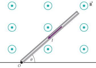
You are given a circular conducting wire loop with one
end cut out and connected to a resistor, R, as shown in
the figure to the right. A metal rod of length l is set at an
initial angle ?0 from the resistor, and then rotates
clockwise about the center of the wire loop with angular
frequency through a uniform magnetic field B
directed into the page. The metal rod stays in contact
with the wire loop at all points of its motion. Unless
otherwise requested, all answers should be in simplified
algebraic form using the above given variables.
(a) Given that the initial angle ?0 is in radians, what is theinitial area of the closed circuit âwedgeâdefined by ?0? (2pts.)
(b) What is the magnetic flux through this initial âwedgeâ areadefined by ?0? (2 pts.)
Starting at time t=0 at position ?0, the rod is rotated clockwisewith angular velocity as shown in
the figure. Given this configuration, answer questions (c)-(g)below:
(c) What is the direction of the induced magnetic field inside theâwedgeâ? (2 pts)
(d) What is the direction of the induced current around the closedcircuit? (2 pts)
(e) What is the magnitude of the induced emf, E in the circuit? (4pts)
(f) What is the magnitude of the induced current in the circuit? (4pts)
(g) What is the power used by the resistor? (4 pts)
(h) The metal rod is now rotated in the opposite direction, i.e. inthe counter-clockwise direction. Given this information, completethe chart below as to what quantities you just calculated change,and what ones do not change. You do not have to show work, justgive the result. No partial credit will be given here. (5pts)
Direction of induced magnetic field inside the âwedgeâ.
Direction of the induced current around the closed circuit.
Magnitude of the induced emf, E in the circuit.
Magnitude of the induced current in the circuit.
Power used by the resistor.
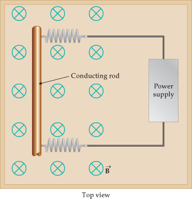
The setup is now modified slightly so that the circular conductingwire loop no longer has a small
section removed as shown in both figures below. This modificationwould allow the metal rod to
continuously rotate on the circular wire loop as clearlyillustrated in the 3D side view. The metal rod
is rotated clockwise, as in the initial part of the problem.
(i) Given this information, complete the chart below. You do nothave to show work, just give the
result. No partial credit will be given here. (5 pts)
Direction of induced magnetic
field inside the âwedgeâ.
Direction of the induced current
around the closed circuit.
Magnitude of the induced emf, E in
the circuit.
Magnitude of the induced current
in the circuit.
Power used by the resistor.
You are given a circular conducting wire loop with one
end cut out and connected to a resistor, R, as shown in
the figure to the right. A metal rod of length l is set at an
initial angle ?0 from the resistor, and then rotates
clockwise about the center of the wire loop with angular
frequency through a uniform magnetic field B
directed into the page. The metal rod stays in contact
with the wire loop at all points of its motion. Unless
otherwise requested, all answers should be in simplified
algebraic form using the above given variables.
(a) Given that the initial angle ?0 is in radians, what is theinitial area of the closed circuit âwedgeâdefined by ?0? (2pts.)
(b) What is the magnetic flux through this initial âwedgeâ areadefined by ?0? (2 pts.)
Starting at time t=0 at position ?0, the rod is rotated clockwisewith angular velocity as shown in
the figure. Given this configuration, answer questions (c)-(g)below:
(c) What is the direction of the induced magnetic field inside theâwedgeâ? (2 pts)
(d) What is the direction of the induced current around the closedcircuit? (2 pts)
(e) What is the magnitude of the induced emf, E in the circuit? (4pts)
(f) What is the magnitude of the induced current in the circuit? (4pts)
(g) What is the power used by the resistor? (4 pts)
(h) The metal rod is now rotated in the opposite direction, i.e. inthe counter-clockwise direction. Given this information, completethe chart below as to what quantities you just calculated change,and what ones do not change. You do not have to show work, justgive the result. No partial credit will be given here. (5pts)
Direction of induced magnetic field inside the âwedgeâ.
Direction of the induced current around the closed circuit.
Magnitude of the induced emf, E in the circuit.
Magnitude of the induced current in the circuit.
Power used by the resistor.
The setup is now modified slightly so that the circular conductingwire loop no longer has a small
section removed as shown in both figures below. This modificationwould allow the metal rod to
continuously rotate on the circular wire loop as clearlyillustrated in the 3D side view. The metal rod
is rotated clockwise, as in the initial part of the problem.
(i) Given this information, complete the chart below. You do nothave to show work, just give the
result. No partial credit will be given here. (5 pts)
Direction of induced magnetic
field inside the âwedgeâ.
Direction of the induced current
around the closed circuit.
Magnitude of the induced emf, E in
the circuit.
Magnitude of the induced current
in the circuit.
Power used by the resistor.