1
answer
0
watching
480
views

6 Oct 2020
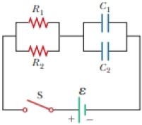
The circuit in Figure P27.41 contains two resistors, R1 = 2.00 kΩ and R2 = 3.00 kΩ, and two capacitors, C1 = 2.00 μF and C2 = 3.00 μF, connected to a battery with emf ε = 120 V. If there are no charges on the capacitors before switch S is closed, determine the charges on capacitors (a) C1 and (b) C2 as functions of time after the switch is closed.
Figure P27.41
Tauseef ShaikhLv10
7 Jan 2021