CS 120 Lecture 6: Digital Logic Circuits

2 Feb 2017
School
Department
Course
Professor
Document Summary
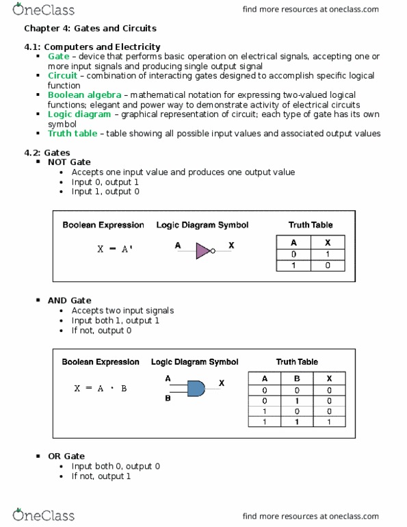
The entirety of the classwork from last class: Using the following elements, create a circuit that inverts the signal (make a not circuit): Remember, the not circuit has the truth table: The arrow at the top is power, and the lines on the bottom are ground. The square with the 0 is the signal input, and the circle with the 1 is the signal output. The transistor connected to the power is the p-gate, which opens (stops flow) when the input is 1, and closes (allows flow) when the input is 0. The transistor connected to the ground is the n-gate, which opens (stops flow) when the input is 0, and closes (allows flow) when the input is 1. Using the following elements, create a nor circuit: This depends on whether the transistors are in parallel or series. The n-gates are in parallel, which means that only one of the gates must be open to be connected to ground.