MECHANICAL ENGINEERING Lecture Notes - Lecture 1: Free Body Diagram, Ansys, Statically Indeterminate

27 Oct 2021
Department
Course
Professor

MECHANICS OF SOLID
SECTION B
1
Contents
Problem Statement .................................................................... 3
Part (a) ........................................................................................ 4
Given: ....................................................................................... 4
Assumption: ............................................................................. 4
Free body diagram: .................................................................. 5
Calculations: ............................................................................. 6
Maximum shear stress: ............................................................ 8
Part (b) ........................................................................................ 9
Given: ....................................................................................... 9
Assumption: ............................................................................. 9
Free body diagram: ................................................................ 10
Calculations: ........................................................................... 11
Maximum shear stress:……………………………………………………….13
Part C-a………………………………………………………………………………….14
3d Model: ……………………………………………………………………….….14
Result: …………………………………………………………………………….....15
Boundary Conditions: …………………………………………………………17
Meshing with Details…………………………………………………………..18
Description of every step ……………………………………………………19

MECHANICS OF SOLID
SECTION B
2
Part C-b………………………………………………………………………………….31
3d Model: …………………………………………………………………..………31
Result: ………………………………………………………………………….…….32
Boundary Conditions: …………………………………………………….…..34
Meshing with Details…………………………………………………………..35
Description of every step ……………………………………………………36

MECHANICS OF SOLID
SECTION B
3
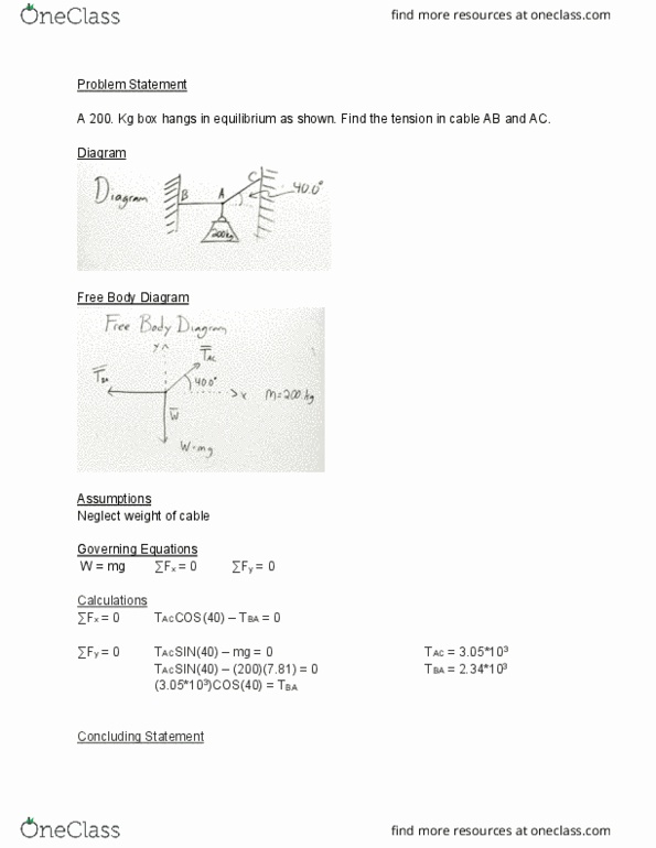
Problem Statement
The shaft AB is fixed at its ends A and B as shown in figure. If it is subjected to the
torques TC = 500N.m and TE = 200N.m shown. Where, segment AD is solid shaft
with 60 mm diameter and made of steel with G = 75 GPa, and segment DB is
hollow shaft with outer diameter of 60mm and inner diameter 30 mm and made
of aluminum with G = 26 GPa. LAC = 1m, LCD = 1.25m, LDE = 1.25m and LEB = 1m.
a) Determine the reactions at A and B. And absolute maximum shear stress in the
shaft.
b) Find the value of TC and TE for which the value of reaction torque at A and B
are equal to last three digits of your registration number. And also calculate
absolute maximum shear stress.
c) Using any FEA package to find reactions and maximum shear stress for (a) and
(b), for simulation take Poisson’s ratio 0.3