ENGR2000 Lecture Notes - Lecture 4: A Aa, Dynamic Pressure, Static Pressure

2 Jul 2018
School
Department
Course
Professor

2nd-Year Fluid Mechanics, Faculty of Science & Engineering, Curtin University
ENGR2000: FLUID MECHANICS
For Second-year Chemical, Petroleum, Civil & Mechanical Engineering
FLUID MECHANICS LECTURE NOTES
CHAPTER 4: THE BERNOULLI EQUATION
4.1 Introduction
We have already noted that the pressure in a fluid is linked to its motion; it is
also linked to the hydrostatic pressure (consider a fluid at rest). Bernoulli’s
equation, written below, defines the link:
p+1
2ρU2+ρgz =const. along a streamline (4.1)
where pis the actual pressure at a location in the flow field, U=|v|is the
speed of the fluid (in the direction of the streamline) at that location and z
is the ‘up’ coordinate (from some horizontal datum) of that location. This
is an especially useful equation although there are limitations as to its use;
these will be discussed after (as a consequence of) its derivation.
4.2 Derivation of the Bernoulli equation
We will use the mass conservation and momentum equations. So, we need a
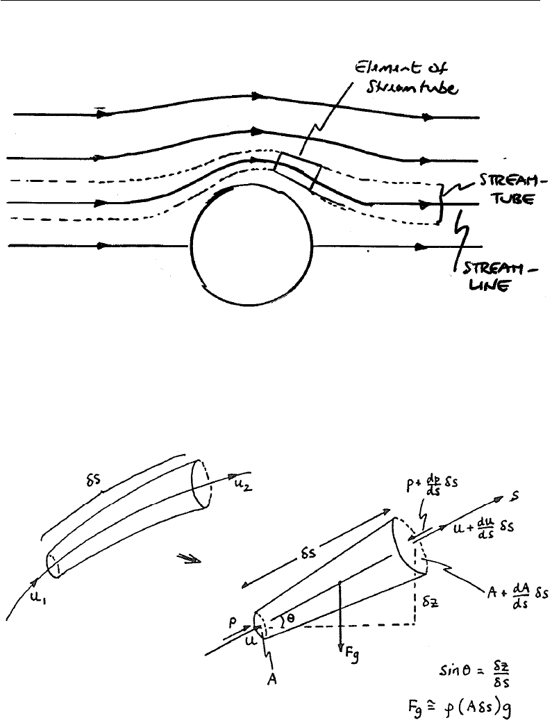
suitable control volume. Consider a stream-tube shown in Fig. X4.1 – it is
thin (so that the flow velocity is constant across a given cross-section) tube
surrounding a streamline in the flow. Note that we can think of the fluid flow
as comprising ‘bundles’ of stream-tubes. Where the flow is fast (streamlines
close together), the stream-tube is thin; conversely, where the flow slows
down, the sam stream-tube becomes thicker (mass-flow conservation).
Chapter 4 −Page 1
find more resources at oneclass.com
find more resources at oneclass.com
2nd-Year Fluid Mechanics, Faculty of Science & Engineering, Curtin University
FIGURE X4.1: Definition of a stream-tube (in flow past a cylinder).
In Fig. 4.1a a stream-tube with (infinitesimal) length δs is shown.
FIGURE 4.1: Stream-tube and infinitesimal CV cut from it.
The same stream-tube is shown schematically in Fig. 4.1b and will be our
control volume. Since δs can be made arbitrarily short, we may consider the
s-axis to be a straight line; the application of the momentum equation will
Chapter 4 −Page 2
find more resources at oneclass.com
find more resources at oneclass.com
2nd-Year Fluid Mechanics, Faculty of Science & Engineering, Curtin University
be along this axis so that we do not have to deal with vector quantities, i.e.
we effectively have a one-dimensional problem.
First, note that if the value of a quantity, eg. D, is known at point s, then we
can write an expression for its value at s+δs by using a Taylor expansion,
viz.:
D(s+δs) = D(s) + δs
1
dD(s)
ds +δs2
2
d2D(s)
ds2+δs3
6
d3D(s)
ds3+.....
Since we can make δs arbitrarily small, (so δs >> δs2>> δs3....), we trun-
cate the above expansion to give a linear approximation:
D(s+δs)≈D(s) + dD(s)
ds δs (4.2)
or upon re-arrangement:
dD(s)
ds ≈D(s+δs)−D(s)
δs
where the approximation becomes exact in the limit, δs →0. (This is, of
course, the definition of differentiation of D, here with respect to s.) We will
use the form of Eqn. 4.2 repeatedly in the following.
We now apply mass conservation and the momentum equation:
(i) Mass Continuity:
Since the flow is parallel to the streamline, flow enters and leaves only through
the end faces of the CV. Using ‘mass flow-rate in = mass flow-rate out’,
having assumed steady and incompressible flow:
ρUA =ρU+dU
ds δsA+dA
ds δs(= ˙m) (4.3)
(ii) Momentum Equation
We use the (scalar) momentum equation in the s-direction. Recall that:
Sum of applied forces = Rate of increase of momentum inside CV
- (momentum flux INTO CV - momentum flux OUT of CV)
(3.7b)
Chapter 4 −Page 3
find more resources at oneclass.com
find more resources at oneclass.com
Document Summary
For second-year chemical, petroleum, civil & mechanical engineering. We have already noted that the pressure in a uid is linked to its motion; it is also linked to the hydrostatic pressure (consider a uid at rest). Bernoulli"s equation, written below, de nes the link: p + This is an especially useful equation although there are limitations as to its use; these will be discussed after (as a consequence of) its derivation. We will use the mass conservation and momentum equations. X4. 1 it is thin (so that the ow velocity is constant across a given cross-section) tube surrounding a streamline in the ow. Note that we can think of the uid ow as comprising bundles" of stream-tubes. Where the ow is fast (streamlines close together), the stream-tube is thin; conversely, where the ow slows down, the sam stream-tube becomes thicker (mass- ow conservation). Figure x4. 1: de nition of a stream-tube (in ow past a cylinder).