1
answer
0
watching
329
views
19 Nov 2019
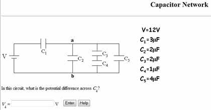
V = 12V c1 = 3 mu F c2 = 2 mu F c3 = 2 mu F c4 = 1 mu F c5 = 4 mu F In this circuit, what is the potential difference across C4? V4 = v

Bunny GreenfelderLv2
8 Jan 2019